Electrical Engineering · Updated June 2026
How to Learn RLC Resonance and Master Filter Circuits with AI Safely
Master series and parallel RLC resonance, Q-factor calculations, frequency response curves, and AC filter circuit configurations using Socratic AI coaching to build engineering intuition safely.

In electrical engineering, telecommunications, and physics, resistor-inductor-capacitor (RLC) circuits are fundamental systems used to select or reject specific signal frequencies. The phenomenon of resonance occurs when the inductive reactance (\(X_L = \omega L\)) and capacitive reactance (\(X_C = \frac{1}{\omega C}\)) are equal in magnitude but opposite in phase, cancelling each other out.
For a series RLC circuit:
- Resonant Frequency (\(\omega_0\)): The frequency at which reactivation cancellation occurs: \(\omega_0 = \frac{1}{\sqrt{LC}}\) rad/s or \(f_0 = \frac{1}{2\pi\sqrt{LC}}\) Hz.
- Impedance (\(Z\)): The total opposition to AC current: \(Z = \sqrt{R^2 + (X_L - X_C)^2}\). At resonance, \(X_L = X_C\), so $Z = R$. The impedance is at its absolute minimum and is purely resistive, which maximizes the current (\(I_{max} = V/R\)).
- Quality Factor (\(Q\)): A measure of the sharpness of the resonant peak: \(Q = \frac{\omega_0 L}{R} = \frac{1}{\omega_0 RC}\). A higher \(Q\) indicates a narrower, sharper peak.
- Bandwidth (\(B\)): The frequency range over which the power is at least half of its maximum value: \(B = \frac{\omega_0}{Q} = \frac{R}{L}\) rad/s.
- Filters: RLC circuits act as filters by passing or blocking certain bands of frequencies:
- Low-pass: Passes low frequencies and blocks high frequencies.
- High-pass: Passes high frequencies and blocks low frequencies.
- Band-pass: Passes a specific band of frequencies centered around \(f_0\).
- Band-stop (Notch): Rejects a specific band centered around \(f_0\).
Because AC circuit calculations involve complex numbers (phasors), angular frequency (\(\omega = 2\pi f\)), and multi-variable equations for filter transfer functions, students frequently ask AI models to compute currents, Q-factors, or resonant frequencies directly. However, relying on AI to solve these equations prevents you from developing the physical understanding of how reactive components store and transfer energy in the time and frequency domains. This guide outlines a Socratic workflow to utilize AI as an AC circuits coach.
Step 1: Navigating Reactance & Resonance Socraticly
Before designing RLC filters, you must understand how inductive and capacitive reactances vary with frequency.
- Inductor Reactance: \(X_L = \omega L\) increases linearly with frequency.
- Capacitor Reactance: \(X_C = 1/(\omega C)\) decreases non-linearly with frequency.
Use this Socratic prompt to check your reactance and resonance intuition:
I am studying series RLC circuits and need to find the resonant frequency. Act as a Socratic electrical engineering tutor. Do not solve for the frequency or write out the formulas directly. Ask me to describe what happens to the inductive and capacitive reactances as frequency approaches zero versus infinity. Then, prompt me to explain the physical condition that defines the point of resonance. Guide me.Step 2: Formulating Quality Factor & Bandwidth Socraticly
The Quality Factor (\(Q\)) represents the ratio of stored energy to dissipated energy per cycle in the circuit. A higher \(Q\) means the circuit is highly selective, making it ideal for tuning applications (like radio receivers), while a lower \(Q\) is used when a wider passband is needed.
Using AI to compute \(Q\) and bandwidth directly prevents you from understanding how changes in resistance affect the selectivity of your filter.
Use this prompt to master selectivity Socraticly:
I am designing a series RLC bandpass filter. I want to narrow the bandwidth of the filter without changing the resonant frequency. Act as a Socratic circuit design coach. Do not perform the calculations or recommend specific component values. Ask me to state the mathematical relationship between bandwidth, quality factor, and resistance. Prompt me to deduce whether I should increase or decrease the resistor value to achieve a sharper filter peak. Guide me.Step 3: Mapping Filter Transfer Functions Socraticly
Filters are characterized by their transfer function \(H(\omega) = V_{out}/V_{in}\). The output voltage is taken across different components depending on the filter type:
- Band-pass: Output taken across the Resistor (\(R\)).
- Band-stop: Output taken across the series LC combination.
- Low-pass: Output taken across the Capacitor (\(C\)) (for simple RC).
- High-pass: Output taken across the Inductor (\(L\)) (for simple RL).
Use this Socratic prompt to analyze transfer functions:
I need to derive the transfer function for an RLC circuit where the output is taken across the capacitor. Act as a Socratic devices tutor. Do not write out the transfer function or perform the algebra. Ask me to explain how the impedance of the capacitor and inductor behave at very low frequencies (DC) and very high frequencies. Then, prompt me to deduce what type of filter this configuration represents based on those behaviors. Guide me.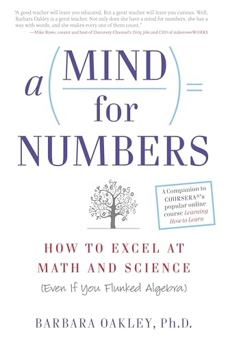
A Mind for Numbers: How to Excel at Math and Science
Dr. Barbara Oakley's actionable guide to unlocking analytical thinking. Perfect for students tackling STEM classes who want to beat procrastination and master complex formulas.
AI Study Pilot receives a small commission from qualifying Amazon purchases at no extra cost to you.Common mistakes
Keep an eye out for these classic pitfalls when studying RLC circuits:
- Confusing series and parallel resonance formulas: In series resonance, impedance is at its minimum ($Z = R$), and current is maximized. In parallel resonance, impedance is at its maximum ($Z = R$), and current from the source is minimized. The formula for \(Q\) also changes: for parallel RLC, \(Q = R\sqrt{\frac{C}{L}} = \frac{R}{\omega_0 L}\). AI models regularly apply series formulas to parallel circuits.
- Neglecting the phase angle: At resonance, the phase angle between voltage and current is zero (\(\theta = 0\), power factor \(\cos\theta = 1\)). Off resonance, the circuit becomes inductive (current lags voltage) or capacitive (current leads voltage). Students often ignore phase shifts when calculating total circuit currents.
- Forgetting that cutoff frequencies are at the -3 dB points: The cutoff frequencies (\(f_1\) and \(f_2\)) are defined where the output voltage drops to \(1/\sqrt{2}\) (about 70.7%) of its maximum value, which corresponds to the half-power points (-3 dB). AI models frequently compute cutoff frequencies incorrectly by assuming they occur at the 50% voltage level. Ask AI: "Quiz me Socraticly on the mathematical definition of cutoff frequencies and why they are called half-power points. Guide me."
FAQ
- Why is the voltage across the inductor/capacitor at resonance much higher than the input voltage? This is called voltage magnification. Since the reactances cancel, the circuit current is limited only by the small resistor. This high current flowing through the inductor and capacitor produces voltages (\(V_L = I X_L\) and \(V_C = I X_C\)) that are \(Q\) times larger than the input source voltage. Prompt: "Socraticly quiz me on the physical mechanism of voltage magnification at resonance and how it relates to energy storage. Guide me."
- What is the difference between active and passive filters? Passive filters use only resistors, inductors, and capacitors and cannot amplify signals. Active filters incorporate operational amplifiers (op-amps) or transistors, allowing for gain, buffer isolation, and the elimination of bulky inductors. Prompt: "Act as a Socratic filter expert. Quiz me on the advantages and frequency limitations of active filters versus passive RLC filters. Guide me."
- How does the damping factor relate to the Quality Factor? The damping factor \(\alpha\) describes how oscillations in the circuit decay over time. In a series RLC circuit, \(\alpha = \frac{R}{2L}\), which is inversely proportional to \(Q\): \(Q = \frac{\omega_0}{2\alpha}\). Prompt: "Socraticly guide me to explain the transient response states (underdamped, critically damped, overdamped) of an RLC circuit using the damping factor. Guide me."
Final recommendation
RLC circuits are frequency-selective systems governed by energy transfer. Do not delegate your resonance equations or filter transfer functions to AI. Instead, draw your phasor diagrams showing reactance vectors, trace your frequency response curves, write out your transfer functions, and leverage Socratic AI sessions to verify your Q-factors, bandwidths, and impedance calculations.
Disclosure: AI Study Pilot may add affiliate links later. We recommend free-first tools where possible and never promise guaranteed grades or outcomes.