Computer Engineering · Updated June 2026
How to Learn Sequential Logic and Design Finite State Machines with AI Safely
Master flip-flop circuits, state transition tables, state reduction, excitation equations, and finite state machine (FSM) designs using Socratic AI coaching safely.
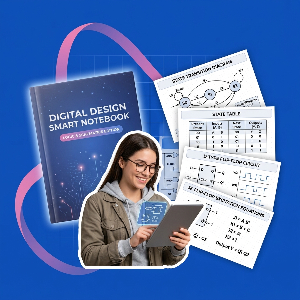
In digital systems design and computer engineering, Sequential Logic is the foundation of processor design, memory elements, and control units. Unlike combinational logic (where outputs depend solely on the current inputs), sequential circuits have "memory"—their outputs depend on both the current inputs and the history of past inputs (the current state).
A sequential system is structured around several critical concepts:
- Memory Elements (Flip-Flops): Circuits like D Flip-Flops or JK Flip-Flops that store a single bit of state, updating their outputs in sync with a clock pulse (edge-triggered).
- State: The binary representation of the circuit's history stored in its flip-flops.
- Finite State Machine (FSM): A mathematical abstraction used to design sequential logic. FSMs come in two primary architectures:
- Mealy Machine: Outputs depend on both the current state and the current inputs.
- Moore Machine: Outputs depend solely on the current state.
- State Transition Diagram: A visual graph where circles represent states and directed arrows represent state transitions labeled with inputs and outputs.
Because mapping state transition tables to hardware gates requires meticulous boolean algebra, Karnaugh map minimizations, and flip-flop excitation calculations, students frequently ask AI models to generate state tables, reduce states, or write Verilog/VHDL code directly. However, letting AI compile these state tables for you prevents you from understanding state assignment optimization and clock setup/hold time limits, which are vital for designing stable silicon hardware. This guide outlines a Socratic workflow to utilize AI as a sequential logic design coach.
Step 1: Mapping State Transition Diagrams Socraticly
Before you can build a sequential circuit, you must translate the problem description (e.g., "detect the sequence 101 in a serial stream") into a state transition diagram. Correctly identifying how many states are needed to "remember" the input sequence is crucial for minimizing flip-flop counts.
Using AI to draw the diagram or list the states directly deprives you of learning how to model state history and partition logical paths.
Use this Socratic prompt to check your state mapping logic:
I am designing a Moore-type sequential circuit that detects the overlapping sequence "110" in a stream of serial bits. Act as a Socratic computer engineering tutor. Do not list the states or draw the transition diagram for me. Ask me to define the meaning of each state (e.g., "State A: Have not seen any ones yet"). Prompt me to trace what happens to the state transition when an unexpected bit is received. Guide me.Step 2: Formulating State Transition Tables Socraticly
Once your transition diagram is defined, you translate it into a State Table listing the Present State, Next State, and Outputs for all possible input combinations. You then perform state reduction to eliminate redundant states and assign binary codes to the remaining states.
Allowing AI to reduce states or assign codes directly prevents you from understanding how binary state encodings affect the complexity of the combinational logic.
Use this prompt to master state table formulation Socraticly:
I am building a JK flip-flop state transition table for a 3-state system. Present states are represented by Q1 and Q2. Act as a Socratic digital logic coach. Do not write the state table or calculate excitation equations. Ask me to compare JK flip-flop excitation values (J and K inputs) for a state change from 0 to 1, and prompt me to apply this logic to fill in the table cells. Guide me.Step 3: Auditing Clock Setup and Hold Times Socraticly
In physical sequential circuits, data must be stable at the input of a flip-flop for a minimum time before the clock edge (setup time, $t{su}$) and after the clock edge (hold time, $th$). Violating these constraints causes metastability, where the flip-flop enters an unstable state and outputs garbage data.
Use this Socratic prompt to check your timing calculations and metastability auditing:
I am calculating the maximum clock frequency for a sequential circuit. The propagation delay of the combinational logic is t_pd, and the flip-flop has a setup time of t_su and a clock-to-Q propagation delay of t_co. Act as a Socratic computer engineering tutor. Do not calculate the clock period or frequency. Ask me to explain the path a data signal takes between two registers, and prompt me to write the inequality that defines the setup time constraint. Guide me.
Rocketbook Smart Reusable Notebook
Eco-friendly, reusable physical notebook that digitizes and syncs your hand-written diagrams and notes directly to your favorite cloud storage for AI-assisted study.
AI Study Pilot receives a small commission from qualifying Amazon purchases at no extra cost to you.Common mistakes
Be on the lookout for these classic pitfalls when studying sequential systems:
- Confusing Mealy and Moore Architectures: Students often mix Mealy and Moore outputs, leading to off-by-one timing errors. Remember: Mealy outputs change immediately when inputs change (asynchronous), while Moore outputs are synchronized with the state registers. Ask AI: "Quiz me Socraticly on comparing the timing hazard and glitch potential of Mealy versus Moore outputs in clock-driven systems. Guide me."
- Overlooking Unused States: If a 3-state system uses 2 flip-flops, there is a 4th state ($2^2=4$) that is unused. If the circuit accidentally enters this unused state (due to noise or power-up), it must be designed to self-start and transition back to a valid state, rather than locking up.
- Ignoring Clock Skew: In large circuits, the clock signal arrives at different flip-flops at slightly different times. This clock skew can cause hold time violations, letting a data signal run through multiple registers in a single clock cycle. Ask AI: "Socraticly quiz me on how clock skew affects setup and hold constraints and how buffer trees are used to mitigate skew. Guide me."
FAQ
- What is the difference between a latch and a flip-flop? A latch is level-sensitive (it changes output whenever the clock is high/low), whereas a flip-flop is edge-triggered (it only changes output on the transition from low-to-high or high-to-low). Prompt: "Act as a Socratic logic design tutor. Quiz me on the difference between level-sensitive latches and edge-triggered flip-flops, and explain why latches are rarely used for state registers. Guide me."
- How does state reduction help circuit design? Reducing the number of states decreases the number of flip-flops required (if the state count drops below a power of 2) or simplifies the combinational logic gates needed to calculate the next states. Prompt: "Socraticly guide me to perform state reduction using an implication chart or equivalence partition. Guide me."
- What is One-Hot state encoding and when is it used? One-Hot encoding uses one flip-flop per state (e.g., 4 states require 4 flip-flops, with only one active at a time:
0001,0010,0100,1000). While it uses more flip-flops, it completely eliminates next-state combinational decoding logic, making it highly efficient for FPGA devices. Prompt: "Quiz me Socraticly on the trade-offs between Binary Encoding, Gray Encoding, and One-Hot Encoding for state machine designs. Guide me."
Final recommendation
Sequential circuits are the ticking heart of modern computing architectures. Do not let AI map your state graphs, minimize your boolean gates, or write your HDL templates. Instead, sketch your state bubbles, fill in your excitation tables manually, audit your timing windows, and leverage Socratic AI sessions to check your state assignment selections, self-starting transitions, and setup/hold time margins.
Disclosure: AI Study Pilot may add affiliate links later. We recommend free-first tools where possible and never promise guaranteed grades or outcomes.