Engineering & mechanics · Updated June 2026
Learn Stress Transformation & Mohr's Circle with AI Safely
Master normal and shear stresses, principal stresses, maximum in-plane shear stress, and Mohr's circle plots using Socratic AI prompting to learn engineering safely.
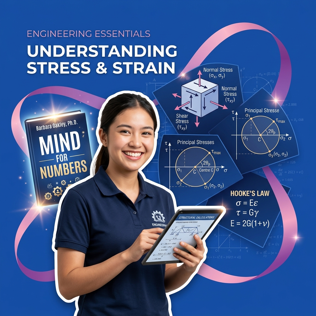
In civil, mechanical, aerospace, and structural engineering, mechanics of materials (or strength of materials) analyzes how solid bodies deform and stress under load. When a structural component (like a beam or shaft) experiences force, the internal stress at any given point varies depending on the orientation of the plane you inspect. Stress Transformation is the mathematical process used to calculate normal and shear stress components on an inclined plane. To make these calculations visual and intuitive, Christian Otto Mohr developed Mohr's Circle—a graphical method that maps stress states to coordinates on a circle.
Because transforming stress tensors and drawing Mohr's Circle involve coordinate plotting, trigonometric transformations, and radius calculations, students often paste stress matrices directly into AI models and ask them to calculate the principal stresses or output the circle diagram. However, large language models are notorious for computational errors when handling geometric geometry, and letting them solve these systems for you bypasses the structural intuition needed to design safe machinery, bridges, and aerospace elements. This guide outlines a safe, Socratic study workflow to use AI as a stress transformation and Mohr's Circle coach.
Step 1: Understanding Stress States and Transformation Equations
A state of plane stress at a point is defined by three stress components: \(\sigma_x\) (normal stress in the x-direction), \(\sigma_y\) (normal stress in the y-direction), and \(\tau_{xy}\) (shear stress on the x-y plane). When we rotate the element by an angle \(\theta\) counterclockwise, the new stress components (\(\sigma_{x'}\), \(\tau_{x'y'}\)) are calculated as:
\[\sigma_{x'} = \frac{\sigma_x + \sigma_y}{2} + \frac{\sigma_x - \sigma_y}{2} \cos 2\theta + \tau_{xy} \sin 2\theta\]
\[\tau_{x'y'} = -\frac{\sigma_x - \sigma_y}{2} \sin 2\theta + \tau_{xy} \cos 2\theta\]
Use this prompt to practice stress transformation equations Socraticly:
I am calculating stress components on a plane rotated 30 degrees counterclockwise. The initial stress state is sigma_x = 80 MPa, sigma_y = 20 MPa, and tau_xy = 30 MPa. Act as a Socratic mechanics of materials tutor. Do not solve the equations or give me the final stresses. Ask me to identify the value of 2*theta, ask me to write down the average normal stress, and guide me through substituting values to compute the transformed normal stress.Step 2: Plotting Mohr's Circle and Finding the Radius
Mohr's Circle maps normal stress (\(\sigma\)) on the horizontal axis and shear stress (\(\tau\)) on the vertical axis (with positive shear stress plotted downward in standard engineering conventions to align rotation directions). To draw it:
- Find the Center (\(C\)): Located on the horizontal axis at:
\[C = (\sigma_{\text{avg}}, 0) = \left(\frac{\sigma_x + \sigma_y}{2}, 0\right)\]
- Plot the Reference Point (\(A\)): Represents the stress state on the vertical x-face: \(A = (\sigma_x, \tau_{xy})\).
- Calculate the Radius (\(R\)): The distance from the center \(C\) to point \(A\):
\[R = \sqrt{\left(\frac{\sigma_x - \sigma_y}{2}\right)^2 + \tau_{xy}^2}\]
Use this prompt to outline Mohr's Circle Socraticly:
I have a state of plane stress with sigma_x = 100 MPa, sigma_y = 40 MPa, and tau_xy = 40 MPa. I want to plot Mohr's Circle. Act as a Socratic engineering coach. Do not write out the circle parameters or draw the diagram. Ask me to find the coordinates of the center C, ask how to find the radius R using the distance formula, and guide me through the calculation steps.Step 3: Determining Principal Stresses and Maximum Shear Stress
The principal stresses (\(\sigma_1, \sigma_2\)) represent the maximum and minimum normal stresses experienced at the point. They occur on the principal planes, where the shear stress is exactly zero. Graphically, these are the leftmost and rightmost points on Mohr's Circle:
\[\sigma_{1,2} = \sigma_{\text{avg}} \pm R\]
The maximum in-plane shear stress (\(\tau_{\text{max}}\)) corresponds to the peak of the circle, which is equal to the radius:
\[\tau_{\text{max}} = R\]
Use this prompt to find principal values Socraticly:
Using my calculated center C = (70, 0) and radius R = 50 for a plane stress state, I want to find the principal stresses and the maximum in-plane shear stress. Act as a Socratic structural mechanics instructor. Do not give me the values. Ask me to explain how the principal stresses relate to the average stress and radius, ask me to perform the additions and subtractions, and guide me to identify the orientation angle of the principal planes.
A Mind for Numbers: How to Excel at Math and Science
Dr. Barbara Oakley's actionable guide to unlocking analytical thinking. Perfect for students tackling STEM classes who want to beat procrastination and master complex formulas.
AI Study Pilot receives a small commission from qualifying Amazon purchases at no extra cost to you.Common mistakes
Keep these typical engineering mechanics pitfalls in mind:
- Sign Conventions for Normal and Shear Stresses: Tensile stress is positive (directed away from the element face), and compressive stress is negative (directed toward the element face). Reversing these signs will shift the center of your circle and lead to wrong coordinates.
- Conflating Physical Rotation with Circle Rotation: A physical rotation of the stress element by an angle \(\theta\) corresponds to a rotation of \(2\theta\) in the same direction on Mohr's Circle. If you rotate your element by \(30^\circ\) on paper, you must rotate \(60^\circ\) on your circle plot.
- Relying on AI Solvers for Matrices: AI models often make arithmetic mistakes when computing square roots for the radius or inverse tangents for the angles. Always sketch the circle manually on a grid to visually check if your principal stress points and radius make geometric sense.
FAQ
- What is the difference between plane stress and plane strain? Plane stress assumes that all stress components on one plane (e.g., the z-plane) are zero (\(\sigma_z = \tau_{xz} = \tau_{yz} = 0\)), typical of thin plates. Plane strain assumes that all strain components on one plane are zero, typical of thick structures like dams or retaining walls.
Prompt: "Socraticly quiz me on the differences between plane stress and plane strain and ask me to identify which models apply to specific engineering components. Guide me."
- How does Mohr's Circle relate to material failure? In ductile materials, yielding is often predicted by the Maximum Shear Stress Theory (Tresca Criterion), which states that yielding occurs when the maximum shear stress (\(\tau_{\text{max}} = R\)) reaches half the yield strength.
Prompt: "Socraticly quiz me on how Mohr's Circle is used to evaluate the Tresca yielding criterion for a given stress state. Guide me."
- How do you draw Mohr's Circle for 3D stress states? A 3D stress state has three principal stresses (\(\sigma_1 \ge \sigma_2 \ge \sigma_3\)). The 3D Mohr's Circle consists of three nested circles drawn between the principal stress coordinates (\(\sigma_1, \sigma_2\)), (\(\sigma_2, \sigma_3\)), and (\(\sigma_1, \sigma_3\)).
Prompt: "Socraticly quiz me on how 3D Mohr's Circles are structured and ask how to find the absolute maximum shear stress from the three circles. Guide me."
Final recommendation
Stress transformation maps the physical limits of structures. Do not let AI tools solve your stress tensors or draw your circles. Instead, identify your normal and shear components, calculate the center and radius systematically on paper, and leverage Socratic AI prompt sessions to audit your sign conventions, rotation angles (\(2\theta\)), and principal boundaries.
Disclosure: AI Study Pilot may add affiliate links later. We recommend free-first tools where possible and never promise guaranteed grades or outcomes.